
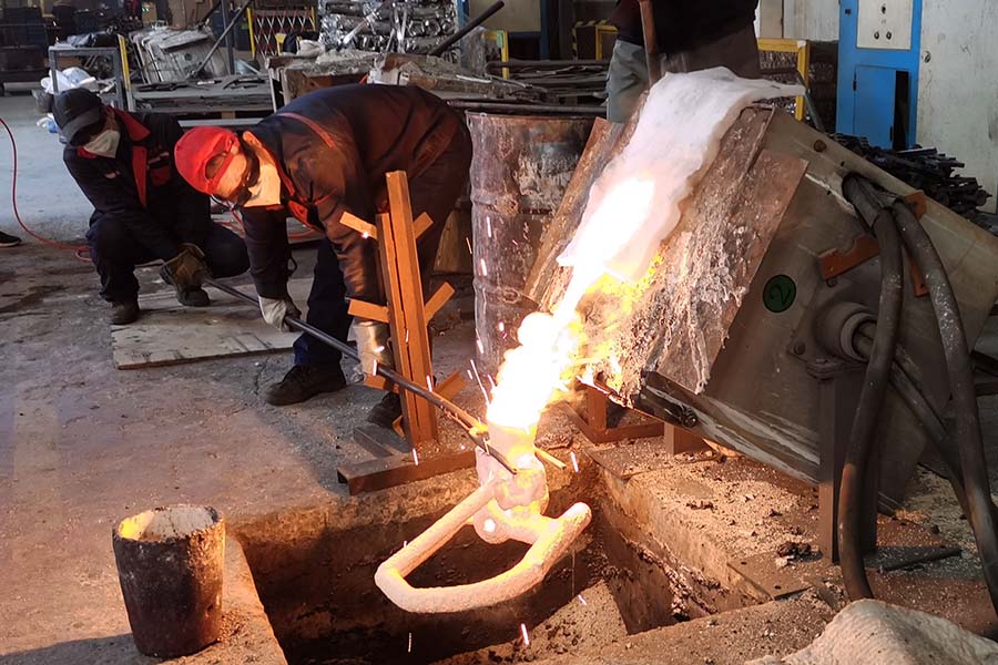
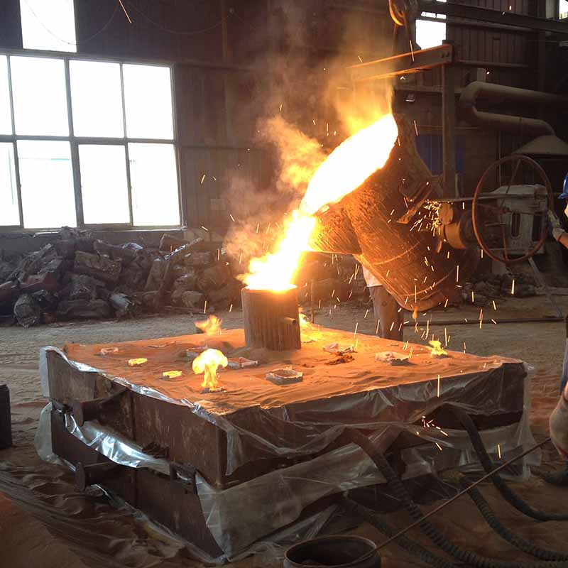
Casting is one of the earliest metal-shaping methods known to human beings. It generally means pouring molten metal into a refractory mould with a cavity of the shape to be made, and allowing it to solidify. When solidified, the desired metal object is taken out from the refractory mould either by breaking the mould or by taking the mould apart. The solidified object is called casting. This process is also called founding, and the modern factory which is focusing on casting metal parts is called foundry.
1. History of Casting Process
The casting process was probably discovered around c 3500 BC in Mesopotamia. In many parts of the world during that period, copper axes and other flat objects were turned out in open moulds made of stone or baked clay. These moulds were essentially in single piece. But in later periods, when round objects were require be made, such moulds were split into two or more parts to facilitate the withdrawal of the round objects The Bronze age (c 2000 BC) brought far more refinement into the casting process. For the first time perhaps, a core for making hollow pockets in the objects was invented. These cores were made of baked clay. Also, the cire perdue or lost wax process was extensively used for making ornaments and fine work.
The casting technology has been greatly improved by the Chinese from around 1500 BC. Before that, there is no evidence of any casting activity found in China. They do not appear to have been great famillar with the cire perdue process nor used it extensively but instead specialized in multi-piece moulds for making highly intricate jobs. They spent a lot of time in perfecting the mould to the last detail so that hardly any finishing work was required on the casting made from the moulds. They probably made piece moulds containing carefully fitted pieces, numbering thirty or more. In fact, many such moulds have been uneartheduring archaeological excavations in various parts of China.
Indus Valley Civilization is also known for its extensive use of casting of copper and bronze for ornaments, weapons, tools and utensils. But there was not much of improvement in the technology. From the various objects and figurines that were excavated from the Indus Valley sites, they appear to have been familiar with all the known casting methods such as open mould, piece mould and the cire perdue process.
Though India could be credited with the invention of crucible steel, not much of iron founding was evident in India. There is evidence that iron founding had started around 1000 BC in Syria and Persia. It appears that iron-casting technology in India has been in use from the times of the invasion of Alexander the Great, around 300 BC.
The famous iron pillar presently located near the Qutb minar in Delhi is an example of the metallurgical skills of ancient Indians. It is 7.2 m long and is made of pure malleable iron. This is assumed to be of the period of Chandragupta II (375-413 AD) of the Gupta dynasty. The rate of rusting of this pillar, which stands outside in open air is practically zero and even the buried portion is rusting at an extremely slow rate. This must have been first cast and then hammered to the final shape.
2. Advantages and Limitations
The casting process is extensively used in manufacturing because of its many advantages. Molten material flows into any small section in the mould cavity and as such, any intricate shape–internal or external–can be made with the casting process. It is possible to cast practically any material be it ferrous or non-ferrous. Further, the necessary tools required for casting moulds are very simple and inexpensive. As a result, for trial production or production of a small lot, it is an ideal method. It is possible in casting process, to place the amount of material where it is exactly required. As a result weight reduction in design can be achieved. Castings are generally cooled uniformly from all sid and therefore they are expected to have no directional properties. There are certain metals and alloy which can only be processed by casting and not by any other process like forging because of the metallurgical considerations. Castings of any size and weight, even up to 200 tons can be made.
However, the dimensional accuracy and surface finish achieved by normal sand-casting process would not be adequate for final application in many cases. To take these cases into consideration, some special casting processes such as diecasting have been developed, the details of which are given in later chapters. Also, the sand-casting process is labour intensive to some extent and therefore many improvements are aimed at it, such as machine moulding and foundry mechanization. With some materials it is often difficult to remove defects arising out of the moisture present in sand castings.
3. Casting Terms
In the follow ing chapters the detals of sand-casting, which represents the basic process of casting would be seen. Before going into the details of the process, defining a number of casting vocabulary words would be appropriate.
Flask – A moulding flask is one which holds the sand mould intact. Depending upon the position of the flask in the mould structure, it is referred by various names such as drag, cope and cheek. It is made up of wood for temporary applications or more generally of metal for long-term use.
Drag – Lower moulding flask
Cope – Upper moulding flask
Cheek – Intermediate moulding flask used in three-piece moulding.
Pattern – Pattern is a replica of the final object to be made with some modifications. The mould cavity is made with the help of the pattern.
Parting line – This is the dividing line between the two moulding flasks that makes up the sand mould. In split pattern it is also the dividing line between the two halves of the pattern
Bottom Board – This is a board normally made of wood, which is used at the start of the mould making. The pattern is first kept on the bottom board, sand is sprinkled on it and then the ramming is done in the drag.
Facing Sand – The small amount of carbonaceous material sprinkled on the inner surface of the moulding cavity to give better surface finish to the castings
Moulding Sand – It is the freshly prepared refractory material used for making the mould cavity. It is a mixture of silica clay and moisture in appropriate proportions to get the desired results and it surrounds the pattern while making the mould.
Backing Sand – It is what constitutes most of the refractory material found in the mould. This is made up of used and burnt sand.
Core – It is used for making hollow cavities in castings.
Pouring Basin – A small funnel-shaped cavity at the top of the mould into which the molten metal is poured.
Spure – The passage through which the molten metal from the pouring basin reaches the mould cavity. In many cases it controls the flow of metal into the mould.
Runner – The passageways in the parting plane through which molten metal flow is regulated before they reach the mould cavity.
Gate – The actual entry point through which molten metal enters the mould cavity.
Chaplet – Chaplets are used to support cores inside the mould cavity to take care of its own weight and overcome the metallostatic forces.
Chill – Chills are metallic objects, which are placed in the mould to increase the cooling rate of castings to provide uniform or desired cooling rate.
Riser – It is a reservoir of molten metal provided in the casting so that hot metal can flow back into the mould cavity when there is a reduction in volume of metal due to solidification
4. Sand Mould Making Procedure
The procedure for making a typical sand mould is described in the following steps:
First, a bottom board is placed either on the moulding platform or on the floor, making the surface even. The drag moulding flask is kept upside down on the bottom board along with the drag part of the pattern at the centre of the flask on the board. There should be enough clearance between the pattern and the walls of the flask which should be of the order of 50 to 100 mm. Dry facing sand is sprinkled over the board and pattern to provide a nonsticky layer. Freshly prepared moulding sand of requisite quality is now poured into the drag and on the pattern to a thickness of 30 to 50 mm. The rest of the drag flask is completely filled with the backup sand and uniformly rammed to compact the sand. The ramming of the sand should be done properly so as not to compact it too hard, which makes the escape of gases difficult, nor too loose, so that the mould would not have enough strength. After the ramming is over, the excess sand in the flask is completely scraped using a flat bar to the level of the flask edges.
Now, with a vent wire, which is a wire of 1-to 2-mm diameter with a pointed end, vent holes are made in the drag to the full depth of the flask as well as to the pattern to facilitate the removal of gases during casting solidification. This completes the preparation of the drag.
The finished drag flask is now rolled over to the bottom board exposing the pattern as shown in the photo. Using a slick, the edges of sand around the pattern is repaired and the cope half of the pattern is placed over the drag pattern, aligning it with the help of dowel pins. The cope flask on top of the drag is located aligning again with the help of the pins. The dry parting sand is sprinkled all over the drag and on the pattern.
A sprue pin for making the sprue passage is located at a small distance of about 50 mm from the pattern. Also,ariser pin if required is kept at an appropriate place and freshly prepared moulding sand similar to that of the drag along with the backing sand is sprinkled. The sand is thoroughly rammed, excess sand scraped and vent holes are made all over in the cope as in the drag.
The sprue pin and the e riser pin are carefully withdrawn from the flask. Later, the pouring basin is cut near the top of the sprue. The cope is separated from the drag and any loose sand on the cope and drag interface of the drag is blown off with the help of bellows. Now, the cope and the drag pattern halves are withdrawn by using the draw spikes and rapping the pattern all around to slightly enlarge the mould cavity so that the mould walls are not spoiled by the withdrawing pattern. The runners and the gates are cut in the mould carefully without spoiling the mould. Any excess or loose sand found in the runners and mould cavity is blown away using the bellows. Now, the facing sand in the form of a paste is applied all over the mould cavity and the runners, which would give the finished casting a good surface finish.
A dry sand core is prepared using a core box. After suitable baking, it is placed in the mould cavity as shown in photo. The cope is replaced on the drag taking care of the alignment of the two by means of the pins. A suitable weight is kept on the cope to take care of the upward metallostatic force during the pouring of molten metal. The mould now, as shown in photo is ready for pouring.
Post time: Dec-25-2020