
Patterns
A pattern is one of the essential tools in the molding process. Its function is to form the mold cavity, and therefore, the pattern directly determines the shape and dimensional accuracy of the casting. To ensure casting quality and improve molding productivity, the pattern must have sufficient strength and rigidity, an appropriate surface finish and dimensional accuracy in line with technical requirements. It should also be easy to use, simple to manufacture, and low in cost.
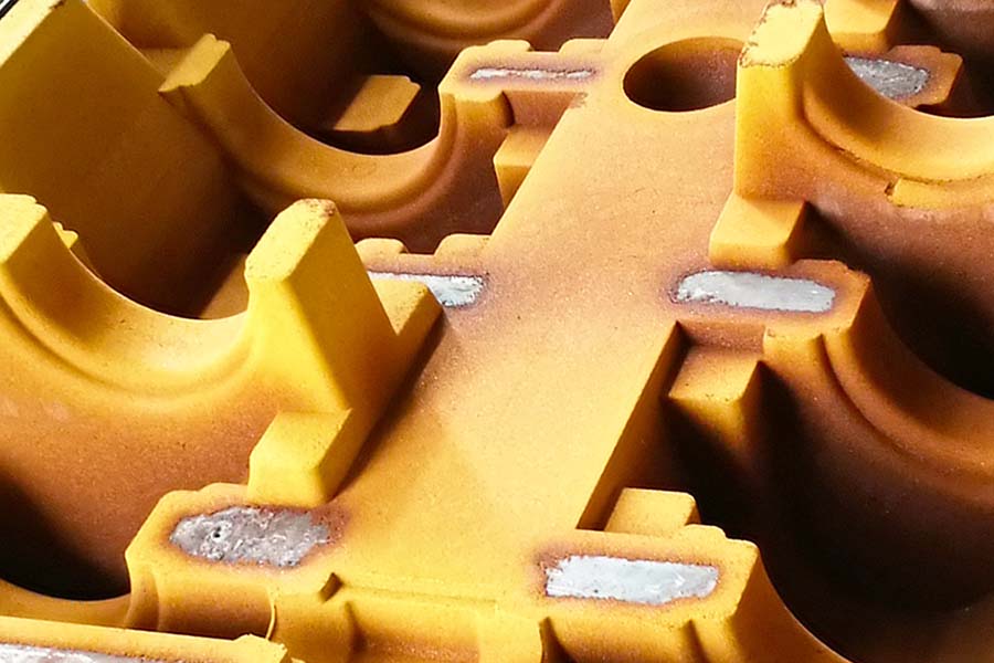
The external shape of a pattern is basically similar to that of the casting, but at places where holes in the casting are to be formed by sand cores, the pattern has no holes but instead protruding core prints (which form core seats in the sand mold).
The dimensions of a pattern must take into account not only the finished part dimensions, but also the process dimensions required for casting (including machining allowances, draft angles, and other process allowances) and the solidification shrinkage rate of the casting material. The dimensions of the pattern can be calculated using the following formula:
Pattern dimension = (Part dimension ± Process allowance) × (1 + Casting shrinkage rate)
In this formula, “+” is applied to convex surfaces of the pattern, while “–” is applied to concave surfaces of the pattern.
Pattern dimensions refer to the dimensions directly forming the casting, excluding the structural dimensions of the pattern itself (such as wall thickness or stiffening ribs). Since core prints and gating/riser patterns do not form part of the casting body, shrinkage allowance is not required for them.
Depending on the structure of the casting, the molding method, and the production volume, patterns can be made from different materials. Based on material, patterns are generally classified into three types: wooden patterns, metal patterns, and plastic patterns.
1. Wooden Patterns
Patterns made of wood are called wooden patterns, and they are among the most widely used. Their advantages include light weight, ease of machining, short production cycle, and low cost. However, they have low strength and hardness, are prone to deformation and damage, and are generally suitable for single or small-batch production.
The wood used for making patterns must have straight grain, toughness, moderate hardness, fine texture, low moisture absorption, minimal swelling/shrinkage, and be free from knots and cracks. Common woods include red pine, white pine, and fir. Before making patterns, the wood should be dried to avoid shrinkage and deformation.
2. Metal Patterns
Patterns made of metal are called metal patterns. They have high strength, accurate dimensions, smooth surfaces, and good wear resistance. However, their production cycle is longer and cost higher, so they are mostly used in batch or mass production.
Common materials for metal patterns include aluminum alloys, cast iron, cast steel, and copper alloys. These materials vary in machinability and mechanical properties, and should be selected based on specific requirements.
Depending on size, patterns may be solid or hollow. Small patterns are usually solid, while medium and large patterns are typically hollow. Hollow metal patterns are usually designed with uniform wall thickness and stiffening ribs inside, ensuring sufficient strength and rigidity.
3. Plastic Patterns
Plastic patterns are made mainly from epoxy resins. Their advantages include smooth surfaces, good stripping performance, resistance to deformation, light weight, wear and corrosion resistance, simple manufacturing process, and short production cycle. However, they cannot be used under heating conditions and emit harmful gases during manufacture. Plastic patterns are generally used for medium and small castings produced in batches, especially those with complex shapes or difficult machining requirements.
Pattern Plates
1. Composition of Pattern Plates
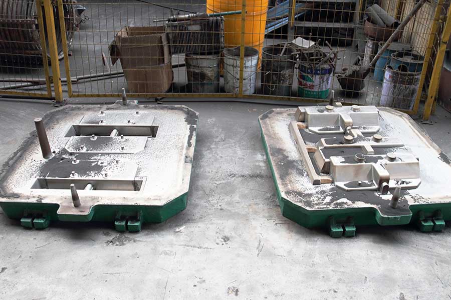
A pattern plate is generally assembled from casting patterns, core print patterns, gating and riser patterns, and a pattern plate (bottom plate) using screws, bolts, and dowel pins. In some cases, the pattern plate is cast as a single unit. Typically, the working surface of the plate forms the parting surface of the mold. The casting pattern, core print pattern, and gating/riser patterns form the external contour of the casting, the core seat, and the gating system cavities, respectively.
Using pattern plates in molding simplifies operations, improves productivity, and ensures precise cavity dimensions. Therefore, pattern plate molding is used not only in mechanized molding for batch or mass production, but also in hand molding for small-batch production when high quality is required.
2. Classification and Structural Features of Pattern Plates
| Type of Pattern Plate | Structural Features | Application Scope |
| Cast Iron Pattern Plate | Material:HT150, HT200, QT500-7 | Bottom plates and frames of single-sided pattern plates |
| Cast Steel Pattern Plate | ZG200-400, ZG230-450, ZG270-500 | Bottom plates of single-sided pattern plates |
| Cast Aluminum Pattern Plate | ZL101, ZL102, ZL104 | Various medium and small pattern plates |
| Plastic Pattern Plate | Usually combined with metal skeletons and frames | Double-sided pattern plates and single-sided pattern plates for small castings |
3. Positioning of Patterns on Pattern Plates and Dimensioning
For single-sided pattern plates, the upper and lower halves of the pattern must be positioned with strict accuracy to avoid mismatch in the casting.
• Reference Line Selection:
The upper and lower molds produced using a single-sided pattern plate are positioned based on the dowel pins and guide pins on the plate. Therefore, the positioning of the patterns on the plate must also be based on these pins. Two reference lines are used: the vertical reference line (through the dowel pin centers) and the horizontal reference line (the line connecting the dowel and guide pins).
• Positioning Method for Upper and Lower Patterns:
Lines are first drawn on the finished halves of the pattern. The halves are paired and clamped together, and holes for dowel pins and bolts are drilled. Lines are then drawn on the upper and lower pattern plates, and bolt holes are drilled. The upper pattern is aligned with the lines and fixed to the upper plate. Using its dowel pin holes, one hole is drilled, and a dowel pin is inserted; then the other hole is drilled. After removing the upper pattern, the upper and lower plates are clamped together, aligned by the guide pin and its connecting line. A hole is drilled using the previously drilled hole as reference, and a dowel pin inserted, followed by the second hole. Finally, the upper and lower patterns are mounted separately onto their plates using the dowel pins, and after verification, secured with screws.
Post time: Sep-18-2025